


EVALUATING THE DECANTER
Where:
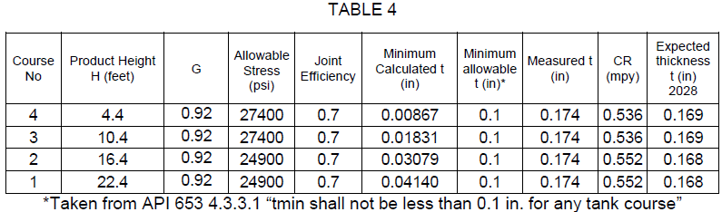
H is the height of liquid from top capacity level to the bottom of the course being evaluated.
D is the nominal tank diameter, in feet.
G is the product´s specific gravity. Let´s use 0.92.
S is the máximum allowable stress in pounds per square inch. According to API 653, S for A36 is 24900 for the first 2 courses and 27400 for the third and higher courses.
E is the efficiency of the welded joint. In this case we will use 0.7 to be more strict, because the year of built is unknown.
(API 653 contains tables of maximum allowable stress for new construction and for in-service tanks. AWWA doesn`t have this provision. AWWA D-100 references the bottom of the course, while API-653 references one foot above the bottom)
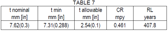
The minimum thickness values required for each are tabulated below.
Remaining life values for each course are tabulated below.
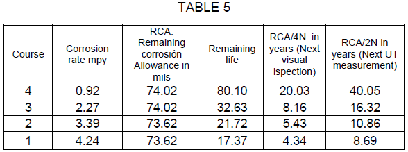
The shell of the decanter can operate safely during 17 years at the current corrosion rate.
EVALUATING THE CONE
There is an equation in AWWA D100 that could be used to evaluate the conical section (AWWA 3.4.3.2), but it is hard to understand, To evaluate this part I use an equation I found in the book of pressure vessel desing by Moss (who in turn took it from Wozniak), page 588, for liquid filled elevated tanks.

The mínimum thickness tc for the cone can be found using the following equations.
At spring line
![]()
![]()
At any point below spring line
![]()
![]()
![]()
DATA FOR THE EXERCISE
W = density = 62.428 lb/cu ft3
H = depth of contents to swing line, ft = 22.4ft
hc = depth of contents from swing line to point of evaluation, ft = 5ft
R = 6.11ft
S = 24900psi
E = 0.7 (Because year of construction is unknown)
C.A. = 0.0625in
RESULTS
T1 = 13619.286 (units are distance2)
T2 = 489.99 (units are distance2)
tc = 0.154in or 0.065in then tc = 0.154in
t min = tc – C.A. = 0.065in then we take it to 0.1in

The conical bottom can operate safely during more than 200 years at the current corrosion rate
EVALUATING THE NOZZLES
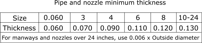
Some owners have in-house standards for the minimum thickness of nozzles. The following is a table used by an operator. Notice the similarity with API 574
AWWA D100 says that “3.10.1 Parts in contact with water. All parts of the structure in contact with water when the tank is filled to the TCL shall have a minimum thickness of 1/4in”, except as shown in Table 16 of AWWA D100”
You can also apply UG-27 ASME , numeral 304.1.2
It says that the mínimum thickness must be the biggest value between the xx thickness vs the longitudinal thickness
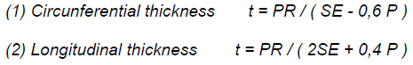
Where
T = minimum required thickness of shell
P = internal design pressure (see UG-21), psi
R = inside radius of the shell course under consideration, in.
S = maximum allowable stress value, psi (see UG-23 and the stress limitations specified in UG-24)
E = joint efficiency for, or the efficiency of, appropriate joint in cylindrical or spherical shells, or the efficiency of ligaments between openings, whichever is less.
Let´s say that we are assessing a 3” nozzle
Then R= 3.5in
Let´s say H = 18ft the P is 14psi aprox.
S = 13800
E= 1 (because the longitudinal Efficiency is 1 because seamless)
Then,
Circunferential Thickness = 1.44×10⁻³
Longitudinal thickness t = 7.21×10⁻⁴
Both this thicknesses are lower than 0,09375, then the mínimum thickness is 0,09375. However, we will use the mínimum thickness of the Shell plate in that course. Then the mínimum allowable thickness is 0,1in
The nozzle can operate safely during 400 years at the current corrosion rate.
EVALUATING THE ROOFBoth AWWA D100 and API 653 have requirements regarding the mínimum thickness for the roof in atmospheric vessels.
According to AWWA D100 “For ground-supported flat-bottom tanks with cone roofs not in contact with water when the tank is filled to the TCL, the minimum thickness of roof plates shall be USS 7 gauge (4.55mm) sheet”
Remaining life of the roof is
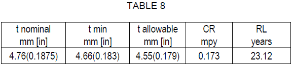
The roof can operate safely during 23 years at the current corrosion rate.
API 653 states “4.2. 1 .2 Roof plates corroded to an average thickness of less than 0.09 in. in any 100 in. 2 area or roof plates with any holes through the roof plate shall be repaired or replaced.” If we work with API 653, then the roof will last more.
CONCLUSIONS
The decanter is fit for service. It is recommended that the next visual inspection is carried out in 4 years and the next UT measurement are carried out in 8 years (See table 5)
As you can see, when inspecting some equipment, you need to know which standards you can use for every part of the vessel. The equipment inspector needs to know several codes and decide which one is the best suited for his case.
A VIDEO COURSE TO PASS API 653
I keep working in a video course for people who want to pass the API 653 or learn more about how to inspect tanks. If you think this offer is for you, please subscribe to the newsletter.
In an article that I wrote in 2017, I offered to write a post about how to handle settlement analysis when the settlement didn´t fit to an optimal cosine curve. Here it is that post.
Let´s see examples of tanks showing different settlement patterns. All of the tanks were in the same tank farm and are real. All of the tanks had 8 points measured.
By reading this, you´ll get a feel of the settlement analysis in tank shells.
THE TANK WITH AN OPTIMAL COSINE CURVE
D=35ft
H=30ft
L=13.74ft
Material = A36
Y = 36000
E = 29000000
The data measured is the following.
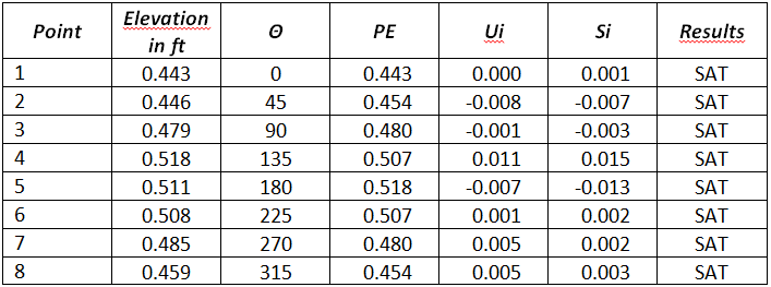
All the points are satisfactory comparing to the allowable settlement calculated from the formula.
Smax =((L^2*Y*11)/2*(E*H)) = 0.043in
Also, a curve exists for this data for which R2 = 0.989
There is nothing to see here. Everything is fine with this tank. If you don´t understand why, go to the article I mentioned above.
THE TILTED TANK
D=25ft
H=24ft
L=9.82ft
Material = Unknown
Y = 30000
E = 29000000
The data measured is the following.
All the points are satisfactory comparing to the allowable settlement calculated from the formula.
Smax =((L^2*Y*11)/2*(E*H)) = 0.023
Also, a curve exists for this data for which R2 = 0.998
Then the settlement is fine.
However, notice the big difference between the highest and lowest point. 93mm. The tank is tilted.
The tank had some 10 years in operation like that. More assessment was recommended. Also, the owner was made aware of the lack o capacity of tilted tanks.
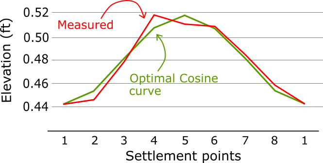
THE TANK IN WHICH ONE POINT IS UNSATISFACTORY
D=20ft
H=24ft
L=7.85ft
Material = Unknown
Y = 30000
E = 29000000
The data measured is the following
Point #2 has a settlement that is higher than the calculated by the formula
Smax =((L^2*Y*11)/2*(E*H)) = 0.015
But a curve exists for this data for which R2 = 0.926
We still need to prove that point 2 meets the settlement criteria. How do we tackle this?
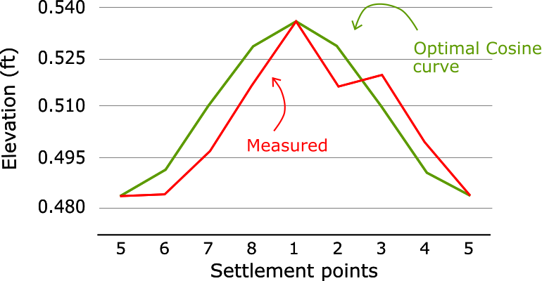
We must measure the maximum out of plane settlement directly from the curve, using the method mentioned in the document “FINAL REPORT ON THE STUDY OF OUT OF PLANE TANK SETTLEMENT” by Andreani. As there exists a close cosine curve, then the graphical method takes that cosine curve into consideration.
I measure the settlement with an image ruler I made in autocad and pasted in Excel. In this case, as there is an optimal cosine curve, you would compare against that cosine curve. The following is the image I made where I lay out the different variables that go into the calculation. The dotted lines need to be where the cosine curve intersects the data curve.
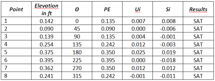
We will use the procedure in B.3.2.2, using the formula.
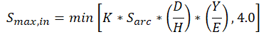
The meaning of each variable in this equation is explained in B.3.2.2 of API 653
The results are tabulated below
Point #2 is definitely out of limits. Partial relevelling, repair or a more torough assessment is needed.
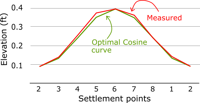
THE TANK WITHOUT AN OPTIMAL COSINE CURVE
D=45ft
H=96ft
L=29.85ft
Material = A283 C
Y = 30000
E = 29000000
The curve for these data shows an R2 = 0.649, which is less than 0.9. The settlement fits poorly to a cosine curve.
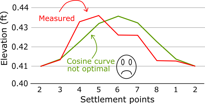
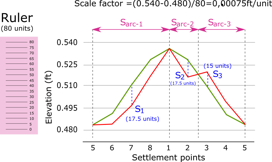
Then you must measure the maximum out of plane settlement directly from the curve, using the method mentioned in the document FINAL REPORT ON THE STUDY OF OUT OF PLANE TANK SETTLEMENT” ” by Andreani. There is no cosine curve this time.
I measure the settlement with an image ruler I made in autocad and pasted it in Excel. The following is the image I made where I lay out the different variables that go into the calculation. The dotted lines need to be where the curve changes direction.
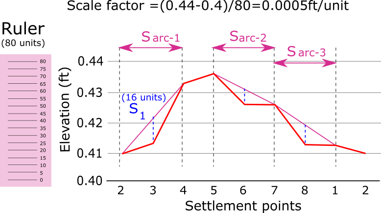
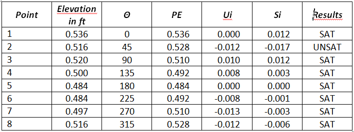
We will use the procedure in B.3.2.2, using the formula.
The meaning of each variable in this equation is explained in B.3.2.2 of API 653
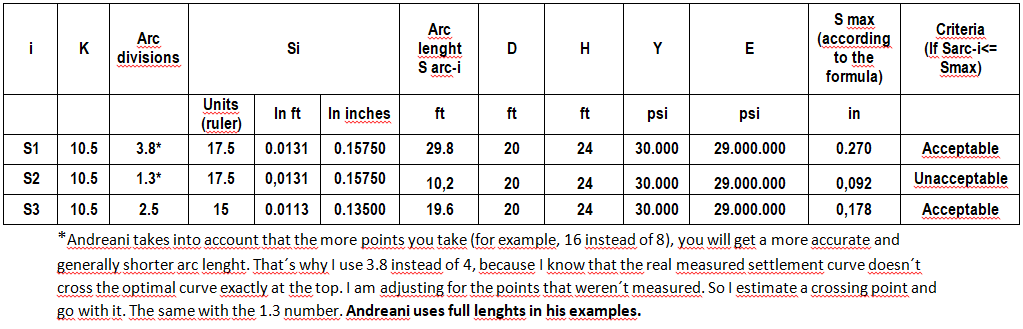
The results are tabulated below. As S1 is obviously the biggest, there is no need to check S2 and S3.
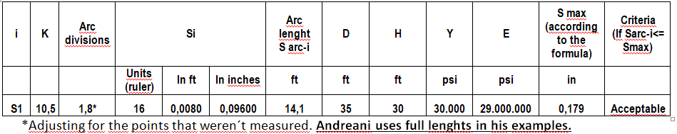
The the settlement is acceptable in each point.
All of this will go into a video course I am preparing about taking the API 653 exam and passing it all along. This video course will also sharpen your inspection skills once you are certified.
By Eng Carlos F Molina
Tank settlement was, for a long time, elusive to me. I got by only whith was needed for the exam. If you are an API 653 inspector, there are many opportunities to do inspection or consulting jobs in small tanks. The following is an introduction to the subject of settlement.
TYPES OF TANK SETTLEMENT
Settlement in tanks can be of several types. API 653 talks about three types: uniform, planar tilt and out-of-plane settlement.
 (more…)
By Carlos F Molina
Here are my thoughts on the numeral 5.1 of API 571, “Determination of Need for Cathodic Protection”
It starts saying that “The need for cathodic protection shall be determined for all aboveground storage tanks.
Determination of Need for Cathodic Protection
Almost any tank of certain size that is in contact with soil will need a cathodic protection in the bottom, because coatings are not perfect (NACE SP0169), so it will be a moment when corrosion starts to act. With more reason if the surface is not coated. (more…)
- Coat the surface with paint so there is no contact between the metal and the electrolyte.
- Coat the surface with a another metal that is sacrificial metal that protects the steel.
- Pasivation.
- Anodization.
- Cathodic protection from sacrificial anodes – no power supplies.
- Cathodic protection by the use of an impressed current from an electrical source.
By Eng. Carlos F Molina
The following article is about API RP 652 for the API 653 certification exam. What do you think is the difference between a lining and a coating? Between a coating and a paint?….. Before you continue reading, share your thoughts in the comment section.
As far as I know, paint is a liquid or paste that, when applied in a substrate, coats a layer over the surface, protects it and then gets to be known as a coating. Any material applied to the internal surfaces of a tank to serve as a barrier to corrosion and/or product , it is known also as a lining. Right now we are going to study linings. If you are preparing to take the API 653 certification exam, do me a favor an read the 652 RP. (more…)