ASME V Radiology part 2
By Carlos F Molina
I am pleased to be back with you for this article. We are reviewing basic radiology for the 653 exam according to ASME V. This is following the radiology first article of this series
Hey. If you know apiexam.com, maybe you have realized that I try to make my articles following the exact order of the Body Of Knowledge. Did you notice then that something was lacking from the latter article? Yes… it was procedure demonstration.
PROCEDURE DEMONSTRATION
As with any other NDE procedure, a radiographic inspection procedure needs to be demonstrated to know the ability of the performer of the examination. It has, like welding procedures, essential and non-essential variables, depending on the radiographic technique selected. Demonstration of the density and image quality indicator (IQI) image re-quirements of the written procedure on production or technique radiographs shall be considered satisfactory evidence of compliance with that procedure.
All NDE procedures used on the job shall be approved by an NDE Level III. The NDE Level III shall select a suitable technique according to the job requirement. All essential and non essential variables shall be mentioned on the procedure. Some values in the procedure may have to be changed after the demonstration.
A test specimen having flaws whose size, location, orientation, quantity and characterization have been determined prior to the demonstration should be known only to the supervising Level III Examiner. The Level III will exercise care to keep the records of those flaws only for himself after demonstration.
Procedure demonstration is defined in article 1 of section V as: A written procedure is demonstrated, to the satisfaction of the Inspector, by applying the examination method using the employer’s written nondestructive examination procedure to display compliance with the requirements of this Section.
[adToAppearHere]
GOING BACK TO THE BOK
required marking
ASME V asks for a system to produce permanent identification on the radiograph traceable to the contract, component, weld or weld seam, or part numbers, as appropriate. The Manufacturer’s symbol or name and the date of the radiograph shall be permanently included on the radiograph. The information not necessarily should appear as radiographic images. In any case, this information shall not obscure the area of interest. If a mistake is commited in the film, how can it be fixed? Does the radiography need to be taken again? No. A tape over the mistake will do it, as long as the change is recorded.
A radiographic film for a tank weld has can be like this:
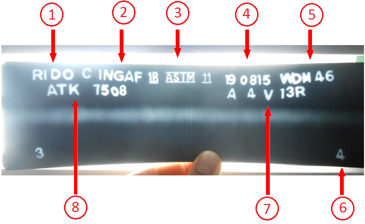
- Name of the radiographic service provider
- Name of the client
- The Image Quality indicator (explained below)
- Date
- Welder´s ID (We use the welder´s initial plus the last 2 digits of his ID)
- Location markers
- Weld ID (When you put this you fullfill the contract, component, weld or weld seam, or part numbers, asked by the standard)
- Tank´s ID
type, selection, number, and placement of IQIs.
WHAT ARE IMAGE QUALITY INDICATORS (IQIs)?
For establishing the quality of an image, an Image Quality Indicator, or penetrameter, is used. The idea is to place a penetrameter (often shortened to penny) on a specimen that is being radiographically tested, to evaluate the sensitivity of the radiograph. Radiographic sensitivity is defined as the smallest or thinnest material change that a radiograph reveals.
Again, sensitivity is a measure of the quality of an image, related to the smallest discontinuity it shows. For example, if a radiograph has 2% sensistivity for a material that is 12mm thick, then the smallest defect that can be found would be:
0,02*12=0,24mm
In the early times of radiographic inspection, you would put, in front of the piece to be inspected, a plate with a perforation the size of the smallest discontinuity you wanted to find in that piece. That was known as a “Hole Type” IQI. However, nowadays the most used type of IQI is the “Wire-type IQI”.
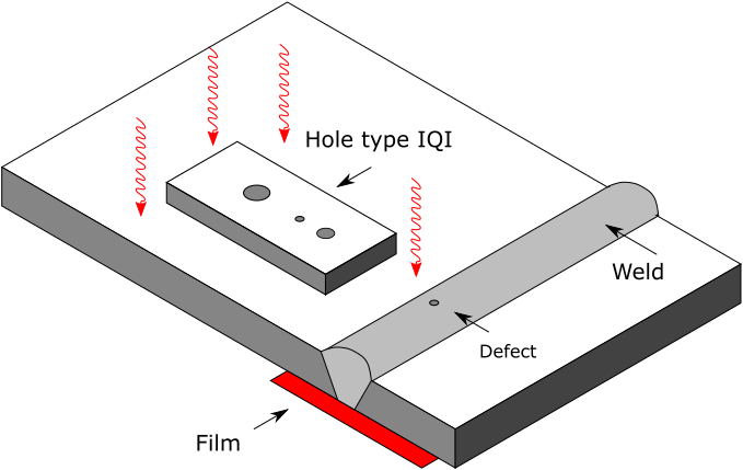
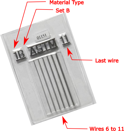
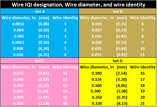
Wire-type IQIs come in four sets (Set A, Set B, Set C, Set D) containing six wires each of different diameters. Sets A, B C, D are selected depending on the thickness of the piece to be evaluated. The thickness on which the IQI is based is the nominal single-wall thickness plus the estimated weld reinforcement not to exceed the maximum permitted by the referencing Code Section. If the piece has 2 walls, the IQI is the same (single wall) but exposure time is double. Wire type IQIs should be placed directly across the weld. The IQI shall be made up of the same material as that of the material to be radiographed or the IQI shall be of a radiographically similar material.
Example of wire type IQI selection: Let´s say you need to select a penny for a piece 6,4mm thick with an 1/8″ reinforcement in each side (The picture of the radiographic film in this article corresponds to that situation). Then the single wall thickness would be 2/4″ = 12,7mm. If you need 2% sensitivity, then multiply 12,7*0,02 = 0,254mm. You go to T-233.2 in ASME V and read through the line of the thickness you need. In this case, the Wire-type essential wire designation is 6. This wire designation corresponds to the set A or B wire type IQI.
If you don´t want to make all of this calculations, go to table T-276 of ASME V, and select directly the wire
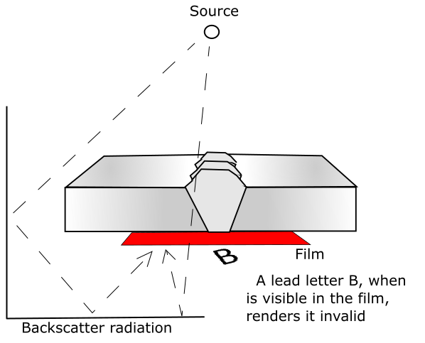
Allowable density control of backscatter radiation
Backscatter radiation happens because some radiation that passes trough the piece can rebound in surfaces behind it, and make white zones that should be dark with defects. A lead symbol “B,” with minimum dimensions of 1⁄2 in. (13 mm) in height and 1⁄16 in. (1.5 mm) in thickness, shall be attached to the back of each film holder during each exposure to determine if backscatter radiation is exposing the film, which will render the film useless (See image below). A light image of the B occurs because the lead letter B acts as shielding that prevents scattered radiation from imaging that portion of the film under the B but, the scatter radiation can expose the rest of the film surface. A dark image of a lead letter B could occur too though in rare ocasions, when backing screens are not used and the lead from the B acts like a lead intensifier screen.
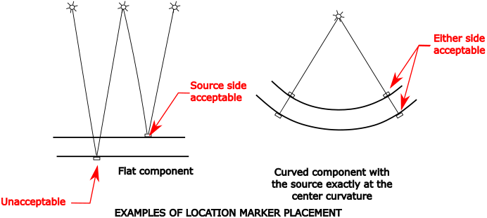
Location markers
Location markers, which are to appear as radiographic images on the film, shall be placed on the part, not on the exposure holder/cassette. ASME V ask for their locations shall be permanently marked on the surface of the part being radiographed, but thi is practically impossible in painted surfaces. Instead you can do a map, in a manner permitting the area of interest on a radiograph to be accurately traceable to its location on the part, for the required retention period of the radiograph. Evidence shall also be provided on the radiograph that the required coverage of the region being examined has been obtained. Example of correct placement of Location Markers can be seen in the figure below. There are more configurations in figure T-275 of ASME V.
[adToAppearHere]
Leave a Comment