


EVALUATING THE DECANTER
Where:
H is the height of liquid from top capacity level to the bottom of the course being evaluated.
D is the nominal tank diameter, in feet.
G is the product´s specific gravity. Let´s use 0.92.
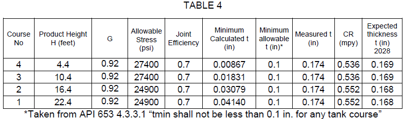
S is the máximum allowable stress in pounds per square inch. According to API 653, S for A36 is 24900 for the first 2 courses and 27400 for the third and higher courses.
E is the efficiency of the welded joint. In this case we will use 0.7 to be more strict, because the year of built is unknown.
(API 653 contains tables of maximum allowable stress for new construction and for in-service tanks. AWWA doesn`t have this provision. AWWA D-100 references the bottom of the course, while API-653 references one foot above the bottom)
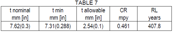
The minimum thickness values required for each are tabulated below.
Remaining life values for each course are tabulated below.
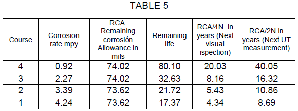
The shell of the decanter can operate safely during 17 years at the current corrosion rate.
EVALUATING THE CONE
There is an equation in AWWA D100 that could be used to evaluate the conical section (AWWA 3.4.3.2), but it is hard to understand, To evaluate this part I use an equation I found in the book of pressure vessel desing by Moss (who in turn took it from Wozniak), page 588, for liquid filled elevated tanks.

The mínimum thickness tc for the cone can be found using the following equations.
At spring line
![]()
![]()
At any point below spring line
![]()
![]()
![]()
DATA FOR THE EXERCISE
W = density = 62.428 lb/cu ft3
H = depth of contents to swing line, ft = 22.4ft
hc = depth of contents from swing line to point of evaluation, ft = 5ft
R = 6.11ft
S = 24900psi
E = 0.7 (Because year of construction is unknown)
C.A. = 0.0625in
RESULTS
T1 = 13619.286 (units are distance2)
T2 = 489.99 (units are distance2)
tc = 0.154in or 0.065in then tc = 0.154in
t min = tc – C.A. = 0.065in then we take it to 0.1in

The conical bottom can operate safely during more than 200 years at the current corrosion rate
EVALUATING THE NOZZLES
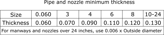
Some owners have in-house standards for the minimum thickness of nozzles. The following is a table used by an operator. Notice the similarity with API 574
AWWA D100 says that “3.10.1 Parts in contact with water. All parts of the structure in contact with water when the tank is filled to the TCL shall have a minimum thickness of 1/4in”, except as shown in Table 16 of AWWA D100”
You can also apply UG-27 ASME , numeral 304.1.2
It says that the mínimum thickness must be the biggest value between the xx thickness vs the longitudinal thickness
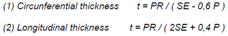
Where
T = minimum required thickness of shell
P = internal design pressure (see UG-21), psi
R = inside radius of the shell course under consideration, in.
S = maximum allowable stress value, psi (see UG-23 and the stress limitations specified in UG-24)
E = joint efficiency for, or the efficiency of, appropriate joint in cylindrical or spherical shells, or the efficiency of ligaments between openings, whichever is less.
Let´s say that we are assessing a 3” nozzle
Then R= 3.5in
Let´s say H = 18ft the P is 14psi aprox.
S = 13800
E= 1 (because the longitudinal Efficiency is 1 because seamless)
Then,
Circunferential Thickness = 1.44×10⁻³
Longitudinal thickness t = 7.21×10⁻⁴
Both this thicknesses are lower than 0,09375, then the mínimum thickness is 0,09375. However, we will use the mínimum thickness of the Shell plate in that course. Then the mínimum allowable thickness is 0,1in
The nozzle can operate safely during 400 years at the current corrosion rate.
EVALUATING THE ROOFBoth AWWA D100 and API 653 have requirements regarding the mínimum thickness for the roof in atmospheric vessels.
According to AWWA D100 “For ground-supported flat-bottom tanks with cone roofs not in contact with water when the tank is filled to the TCL, the minimum thickness of roof plates shall be USS 7 gauge (4.55mm) sheet”
Remaining life of the roof is
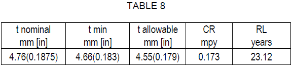
The roof can operate safely during 23 years at the current corrosion rate.
API 653 states “4.2. 1 .2 Roof plates corroded to an average thickness of less than 0.09 in. in any 100 in. 2 area or roof plates with any holes through the roof plate shall be repaired or replaced.” If we work with API 653, then the roof will last more.
CONCLUSIONS
The decanter is fit for service. It is recommended that the next visual inspection is carried out in 4 years and the next UT measurement are carried out in 8 years (See table 5)
As you can see, when inspecting some equipment, you need to know which standards you can use for every part of the vessel. The equipment inspector needs to know several codes and decide which one is the best suited for his case.
A VIDEO COURSE TO PASS API 653
I keep working in a video course for people who want to pass the API 653 or learn more about how to inspect tanks. If you think this offer is for you, please subscribe to the newsletter.
I GOT A PHONE CALL ONE DAY FROM A FRIEND WHO was working in a new construction project with tanks and piping. He told me how the tanks he was working with 2 years old and had tilted flanges in its nozzles.
Pipefitters had a problem, because they would have to degrade their accesories to build the connecting pipe. But when we were talking we discovered that the tilting was too big according to API 650.
Something had to be done about it.
But how to do it without testing the entire tank again?
I remember once when a contractor forgot to install a manhole and discovered it after hydrostatic test (yes, it happens). When installed, the manhole´s flange wasn´t machined according to the standard.
We couldn`t carry on another hydrostatic test, so we decided to ask the contractor for an hydrostatic test of the flange only.
How?
Although it seems difficult, it is not.
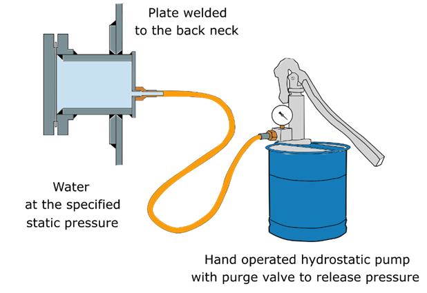
Most of the nozzles and manholes of a tank, if they are not the IFR type, when looked from the inside, show an extensión of the pipe. Let`s call it “back of the neck”.
What you can do, is that you can weld a plate with filling facilities to the “back of the neck”. Then put the lid of the manhole in position and fill the space with water.
The water then can be pressurized using a positive displacement hand pump. It is important that the pump be hand operated, because of the low water volume involved. If you use a powered pump, and you are careless with the pressure gage, you could make the nozzle blow up and you could be in danger.
So, what to do with the tilted flanges in the nozzles of my friend?.
The first thing that I would do is to try and remove the flange from the nozzle and reweld it in a better position to fit the tolerance given by the standard. If that can be done, then you can test the new weld only, with an arrangement like the one before.
What to do when you don´t want to weld anything?
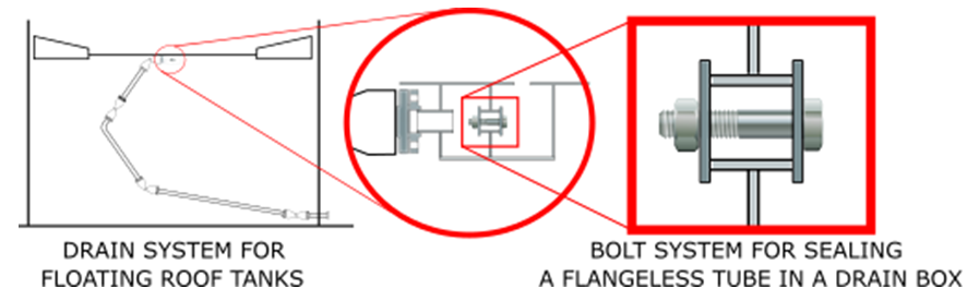
Once when we had to hydrostatically test an articulated drain from an internal floating roof (one of those which use swivel joints). In these roofs, there is a Little box welded under the center of the roof that acts as a collector of the rain.
The complete drain ends in a flanged nozzle situated in the Shell. But, there is no flange in the collector box underneath the roof. How to seal that end of the drain for an hydrostatic test?
By using a setup like the one drawn below (specially with small nozzles)
But what if is the neck of the nozzle that is too tilted? And what you do if you already made the hydrostatic test?
That would be a little more difficult, but not imposible.
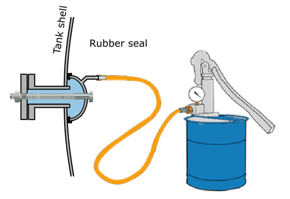
You would have to build an enclosure having the same curvature of the Shell so you can put it against the Shell. The seal between the 2 surfaces can be accomplished using a foam rubber. Then you can put some threaded tie rods. As seen in the picture. Then you can test the new nozzle only and not the tank again.
Everything is possible. If you forget to install a nozzle, you can install it after hydrostatic test if you know what you are doing.
NEW COURSE
In the next months, I´ll be publishing a course on how the pass the API 653 exam on the first try. It will save a lot of money to the people interested. If you want more information, please subscribe to my email list in the box below.
In an article that I wrote in 2017, I offered to write a post about how to handle settlement analysis when the settlement didn´t fit to an optimal cosine curve. Here it is that post.
Let´s see examples of tanks showing different settlement patterns. All of the tanks were in the same tank farm and are real. All of the tanks had 8 points measured.
By reading this, you´ll get a feel of the settlement analysis in tank shells.
THE TANK WITH AN OPTIMAL COSINE CURVE
D=35ft
H=30ft
L=13.74ft
Material = A36
Y = 36000
E = 29000000
The data measured is the following.
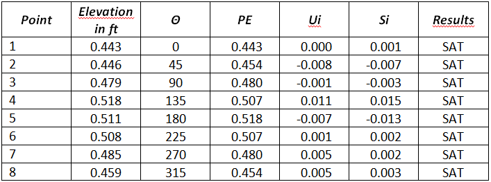
All the points are satisfactory comparing to the allowable settlement calculated from the formula.
Smax =((L^2*Y*11)/2*(E*H)) = 0.043in
Also, a curve exists for this data for which R2 = 0.989
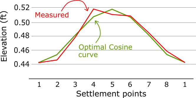
There is nothing to see here. Everything is fine with this tank. If you don´t understand why, go to the article I mentioned above.
THE TILTED TANK
D=25ft
H=24ft
L=9.82ft
Material = Unknown
Y = 30000
E = 29000000
The data measured is the following.
All the points are satisfactory comparing to the allowable settlement calculated from the formula.
Smax =((L^2*Y*11)/2*(E*H)) = 0.023
Also, a curve exists for this data for which R2 = 0.998
Then the settlement is fine.
However, notice the big difference between the highest and lowest point. 93mm. The tank is tilted.
The tank had some 10 years in operation like that. More assessment was recommended. Also, the owner was made aware of the lack o capacity of tilted tanks.
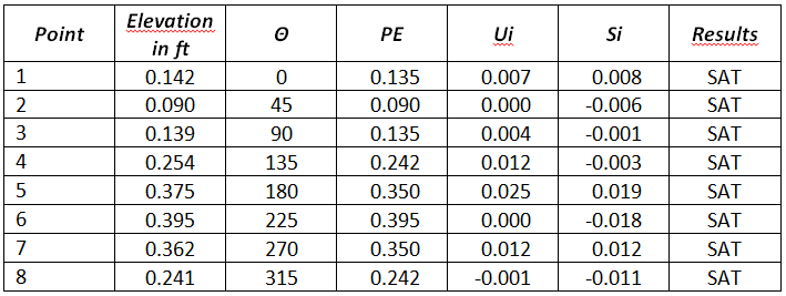
THE TANK IN WHICH ONE POINT IS UNSATISFACTORY
D=20ft
H=24ft
L=7.85ft
Material = Unknown
Y = 30000
E = 29000000
The data measured is the following
Point #2 has a settlement that is higher than the calculated by the formula
Smax =((L^2*Y*11)/2*(E*H)) = 0.015
But a curve exists for this data for which R2 = 0.926
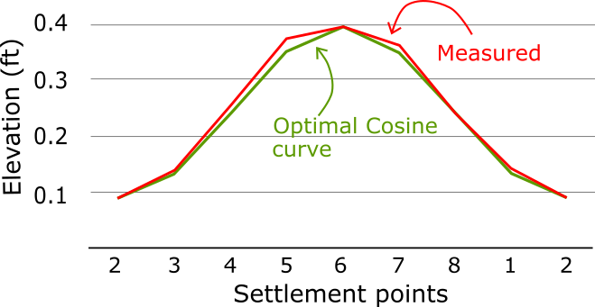
We still need to prove that point 2 meets the settlement criteria. How do we tackle this?
We must measure the maximum out of plane settlement directly from the curve, using the method mentioned in the document “FINAL REPORT ON THE STUDY OF OUT OF PLANE TANK SETTLEMENT” by Andreani. As there exists a close cosine curve, then the graphical method takes that cosine curve into consideration.
I measure the settlement with an image ruler I made in autocad and pasted in Excel. In this case, as there is an optimal cosine curve, you would compare against that cosine curve. The following is the image I made where I lay out the different variables that go into the calculation. The dotted lines need to be where the cosine curve intersects the data curve.
We will use the procedure in B.3.2.2, using the formula.
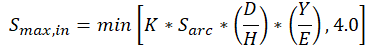
The meaning of each variable in this equation is explained in B.3.2.2 of API 653
The results are tabulated below
Point #2 is definitely out of limits. Partial relevelling, repair or a more torough assessment is needed.
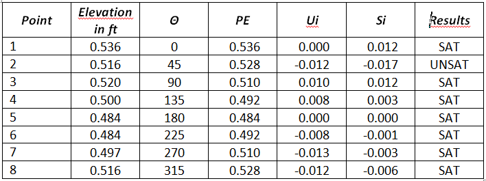
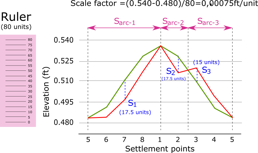
THE TANK WITHOUT AN OPTIMAL COSINE CURVE
D=45ft
H=96ft
L=29.85ft
Material = A283 C
Y = 30000
E = 29000000
The curve for these data shows an R2 = 0.649, which is less than 0.9. The settlement fits poorly to a cosine curve.
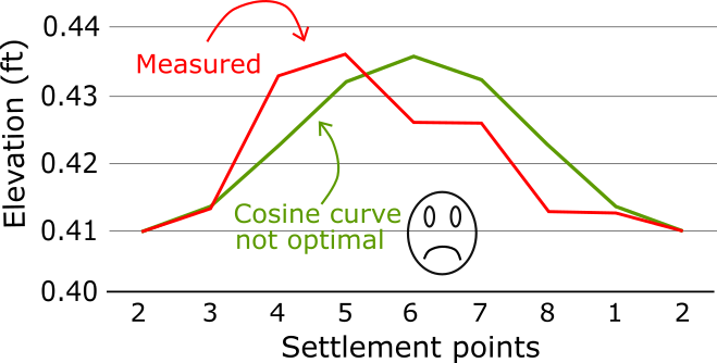
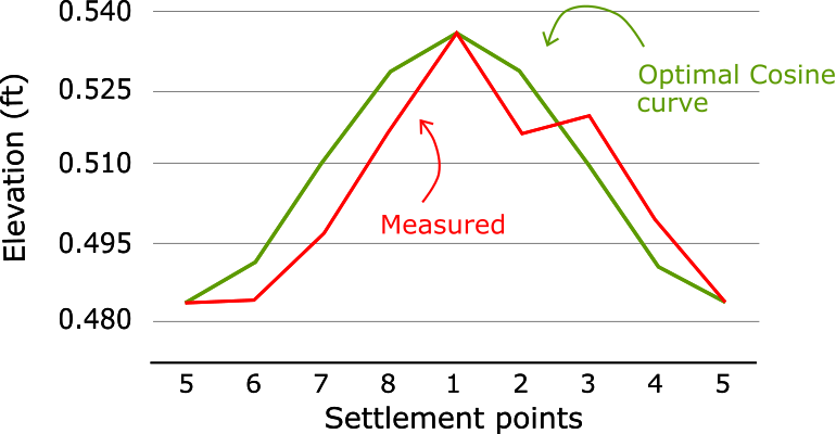
Then you must measure the maximum out of plane settlement directly from the curve, using the method mentioned in the document FINAL REPORT ON THE STUDY OF OUT OF PLANE TANK SETTLEMENT” ” by Andreani. There is no cosine curve this time.
I measure the settlement with an image ruler I made in autocad and pasted it in Excel. The following is the image I made where I lay out the different variables that go into the calculation. The dotted lines need to be where the curve changes direction.
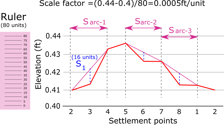
We will use the procedure in B.3.2.2, using the formula.
The meaning of each variable in this equation is explained in B.3.2.2 of API 653
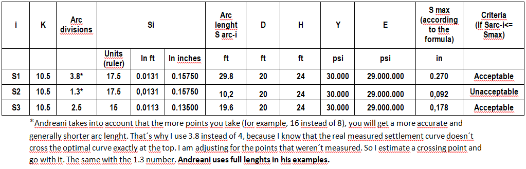
The results are tabulated below. As S1 is obviously the biggest, there is no need to check S2 and S3.
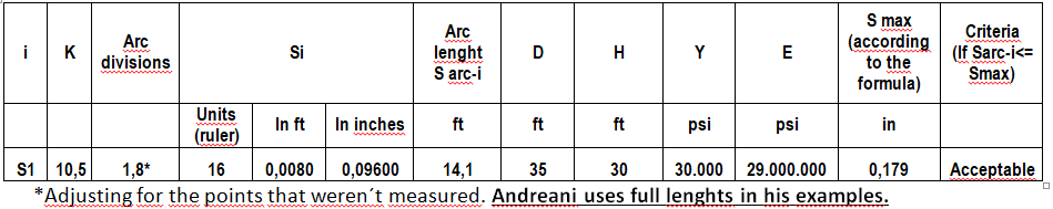
The the settlement is acceptable in each point.
All of this will go into a video course I am preparing about taking the API 653 exam and passing it all along. This video course will also sharpen your inspection skills once you are certified.
By Carlos Molina (Neiva, Colombia)
The ISO 12944 Standard, “Paints and varnishes — Corrosion protection of steel structures by protective paint systems”, is quickly becoming the gold standard of corrosion control on a global scale, and swiftly replacing regional standards of corrosion control. It is useful for owners of assets such as pipes and tanks who have a maintenance schedule.
ISO 12944 grants you…
• … confidence in the specified corrosion control measures taken.
• … the possibility to have a standardized approach for the selection of coating systems.
• … the chance to verify that a coating system proposed is fit for purpose.
ISO 12944 has 8 parts, which are the following:
Part 1: General introduction
Part 2: Classification of environments
Part 3: Design considerations
Part 4: Types of surface and surface preparation
Part 5: Protective paint systems
Part 6: Laboratory performance test methods and associated assessment criteria
Part 7: Execution and supervision of paintwork
Part 8: Development of specifications for new work and maintenance
ISO 12944 enlists several different examples of coating systems according to the corrosivity of the environment and the intended durability. This information can be found in tables A.1 to A.8 in Annex A of part 5. These systems have a proven track record. The standard, however, doesn´t intend to be a comprehensive list of all the systems available.
To understand it, it is necessary to have a certain background in coatings.
How to select a coating system for your facility?
(the steps are taken directly from ISO 12944)
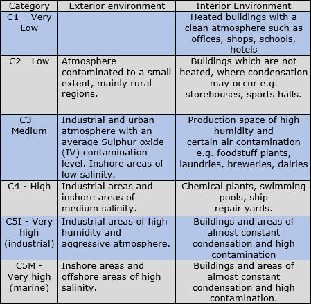
Step 1. Determine the corrosivity category of the environment where the structure will be located most of the time.
ISO 12944 (part 2) lists the corrosivity of the environment according to the following table:
On the other part, for submerged or buried structures, ISO 12944 provides the following classification:
Im1 – fresh water (examples: Instalaciones rivereñas, plantas hidroeléctricas)
Im2 – seawater or brackish water (examples: compuertas, muelles, estructuras offshore, pasos de agua)
Im3 – buried (examples: underground tanks, buried pipes, stilts)
Step 2. Establish if there are any special conditions that result in a higher corrosivity (known as “microclimate” in ISO 12944 part 2).
Step 3. Select the desired durability of the coatings system.
- a) low (L): 2 to 5 years;
- b) medium (M): 5 to 15 years;
- c) high (H): more than 15 years.
Step 4. Look in Annex A for the relevant table. Tables A.2 to A.5 give proposals for different generic types of paint system for corrosivity categories C2 to C5, while Table A.1 gives an overview of the contents of Tables A.2 to A.5.
Step 5. Identify in the table the coating system with the required durability.
Step 6. Select the best sytem, having in mind the surface preparation method.
Step 7. According to ISO12944, “Consult the paint manufacturer in order to confirm the choice and to determine what commercially available paint system(s) correspond to the paint system selected”
Each manufacturer produces one or more coating systems compliant with ISO 12944. That means that every manufacturer has several brands of primer, intermediate and finish paints.
Some manufacturers use the same system for similar applications so many times that these systems have started to have a name of their own. For example, almost all of the manufacturers have a “tanklining” system.
In practice, some systems have much more than the specified 15 years of durability. ISO 12944 states: “In general terms, increasing the total dry film thickness and the number of coats will extend the durability of a paint system. In addition, the choice of a system designed for a corrosivity category “higher” than the one envisaged will provide higher durability when such a system is used in a lower-corrosivity environment.”
EXAMPLE
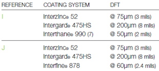
Let´s verify the coating systems proposed by Hempel, PPG Industries and International Paint, for a steel structure situated next to the sea.
Corrosivity category: C5M
Durability: Medium
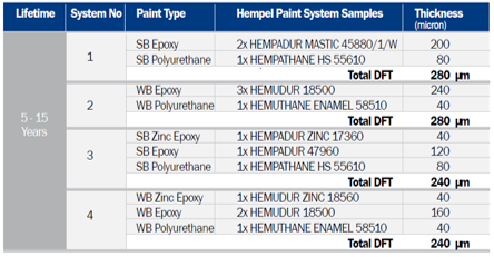
HEMPEL
INTERNATIONAL PAINT
PPG INDUSTRIES
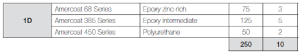
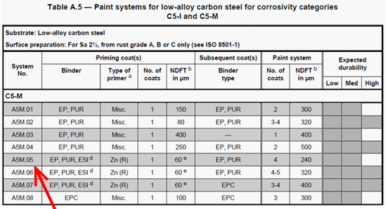
Let´s check against ISO 12944
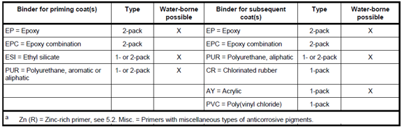
Let´s look in table A5 of ISO 12944 for the C5M category (have in mind that this table is for Low-alloy carbon steel prepared to Sa 2½, from rust grade A, B or C). The proposed systems are equivalent to system A5M.05 included in the ISO standard.
There is a long debate in projects about this.
Should I coat my tank before, or after hydrotesting?
Contractors usually want to coat before hydro, because disassembling and assembling scaffolds takes time.
The short answer is that you should not coat before hydro, because coatings have hole bridging capabilities.
This fact is mentioned in API 652.
However, there are times that you can coat before. (more…)
By Eng Carlos F Molina
Tank settlement was, for a long time, elusive to me. I got by only whith was needed for the exam. If you are an API 653 inspector, there are many opportunities to do inspection or consulting jobs in small tanks. The following is an introduction to the subject of settlement.
TYPES OF TANK SETTLEMENT
Settlement in tanks can be of several types. API 653 talks about three types: uniform, planar tilt and out-of-plane settlement.
 (more…)