Shell calculations for reconstructed tanks (2 of 2)
By Carlos Molina
Last time we saw the basics of shell calculations for reconstructed tanks. Today we will make some practice exercises on determining thicknesses for reconstructed tanks
The book of knowledge says this about reconstructed tanks:
The inspector should be able to determine the minimum thickness of the shell of a reconstructed tank. The inspector should be able to:
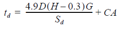
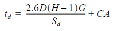
c) Calculate “td”, design shell thickness (API-650, 5.6.3.2, for tanks of 200 foot diameter and smaller)
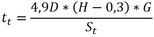
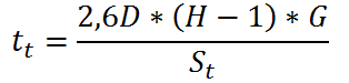
d) Calculate “tt”, hydrostatic test shell thickness (API-650, 5.6.3.2)
We have seen an advance to this issue in the article we had on calculating joint efficiencies, but we will have a further look to the formulas that appear there.
Formulas for the calculation of Minimum Thickness for Reconstructed Tank Shells
The minimum thickness of the shell of a reconstructed tank, is given by the following formulas found in
In International System (SI) units
In United States Customary System (USC) units
Td is the shell design thickness (mm and inches)
Tt is the hydrostatic test shell thickness (mm and inches)
D is the nominal tank diameter (m and ft)
H is the design liquid level (m and ft)
= is the height from the bottom of the course under consideration to the top of the shell including the top
angle, if any; to the bottom of any overflow that limits the tank filling height; or to any other level specified by
the Purchaser, restricted by an internal floating roof, or controlled to allow for seismic wave action.
G is the design specific gravity of the liquid to be stored, as specified by the Purchaser
CA is the corrosion allowance (mm and inches)
Sd is the allowable stress for the design condition (Mpa and psi)
St is the allowable stress for the hydrostatic test condition (Mpa and psi)
PRACTICE EXERCISES
Let´s consider the following example
Example 1. A tank is completely de-seamed and the reconstructed using A283 Gr C steel plates for the shell. Product stored is Texas Crude Oil at 60°F (G= 0,918), CA is 1/8″, and the diameter of the tank is 28,6m. Design liquid level is 9,5m. Plates to be used are 6ft high. Which are the minimum thicknesses for the first shell course for the design and the hydrostatic test condition?
Variables
![]() =?
=?
![]() =?
=?
D = 28,6m
H = 9,5m
G = 0,918
CA = 0,125″
Sd = 137Mpa
St = 154Mpa
E = 1 beacuse the tank is completely de-seamed
Using the formula to calculate the minimum thickness for the design condition, we have:
![]()
And for the hydrostatic test condition:
![]()
Example 2. A tank built in 1970 is dismantled and later reconstructed using A283 Gr C steel plates for the shell. Product stored is vehicle gasoline at 60°F (G = 0,739), CA is 3mm, and the diameter of the tank is 15,6m. Design liquid level is 12,5m. Plates to be used are 6ft high. Which are the minimum thicknesses for each shell course for the design and the hydrostatic test condition if the tank wasn´t completely de-seamed?
![]()
=?
![]() =?
=?
D = 15,6m
H = 12,5m
G = 0,739
CA = 0
Sd = 137Mpa
St = 154Mpa
E = 0,85 according to Table 4.2 of API 653, given that the tank wasn´t completely de-seamed. This is a hint at the fact that this formulas hide the E variable, because it is 1 for de-seamed tanks as by default in new tanks.
Using the formula to calculate the minimum thickness for the design condition, we have:
![]()
And for the hydrostatic test condition:
![]()
You can see the E variable in the lower portion of the equation.
Example 3. A tank of unknown material was completely de-seamed and reconstructed with the following measures: D = 58m, H = 27ft. Product is water and corrosion allowance is 0,1″. Samples of the tank shell material are taken and yield stenght is found to be 32000psi, while tensile strenght is found to be 56000psi. Which is the minimum thickness for design and hydrostatic conditions? Use USC unit of systems.
![]() =?
=?
![]() =?
=?
D = 58m = 190ft
H = 27ft
G = 1
E = 1
CA = 0,1″
For the calculation of Sd, have in mind what API 653 8.4.2 says
For material not listed in Table 5-2, an allowable stress value of the lesser of 2/3 yield strength or 2/5 tensile strength shall be used.
Then
Sd is the lesser of 2/3*32000 = 21333psi or 2/5*56000 = 22400psi
For tanks of unknown material, have in mind what API 653 8.4.3 says regarding St
For material not listed in Table 5-2, an allowable stress value of the lesser of 3/4 yield strength or 3/7 tensile strength shall be used.
Then
St is the lesser of 3/4*32000 = 24000psi or 3/7*56000 = 24000psi
With these data, we can solve for the design condition:
![]()
And for the hydrostatic test condition:
![]()
Most API 653 exams contain questions that require you to pick out S values from one of Table 4.1 of API 653 of table 5.2 od API 650. Make sure to use table 5.2 of API 650 for new and reconstructed tanks.
[adToAppearHere]
That´s all and I hope you liked it.
Latest comments
It is the same method, but less height. For every courses, position yourself one foot over the lowest edge of the course.
- Carlos F. MolinaDear Sir, My question is that if we calculate thickness of one shell course of new tank by one foot method, then how the thickness of other courses will be calculate.? for example 1st shell course thickness=8 mm 2nd shell course=? , 3rd shell course=? Because as height increases thickness reduce.
- Adnan