Introduction to weld spacing in tanks
By Carlos Molina
Following with the subjects that you should study for the exam, today we will have a short explanation of the reason behind some of weld spacings in tank elements. Boy, I have to tell you, thinking for this article was difficult, because it involves many figures and tables that are present in the API 650 and API 653 standards. And writing it was more difficult, because of the little time I have (As most of you in the Oil and Gas Field).
First let me ask you a question: In which plane are tank shell stresses higher, in a vertical or an horizontal plane?
Weld spacing in tanks depends on several factors. First, the extent of the HAZ (Heat affected zone) of a weld, in which the magnitude of property change depends primarily on the base material, the weld filler metal, and the amount and concentration of heat input by the welding process. And second, and most importantly, weld spacing depends on the magnitude of the stress of the joint being considered.
[adToAppearHere]
After this short intro, let´s go to the meat. That´s it, what the BOK for the API 653 says is this:
The inspector should be familiar with determining the sizes and spacing of welds for shell openings to the extent of being able to use the information in the following Figures and Tables:
a) API-650, Figures 5-7A, 5-7B, 5-8, 5-9, 5-12, 5-14, 5-16, 5-17, 5-19, 5-20, 5-21
b) API-650, Tables 5-6, 5-7, 5-9
c) API-653, Figures 9-1, 9-2, 9-3A, 9-3B
Watching this tables and figures in the standards, you can see that questions for them will rather be made in the open book part of the exam, as difficult it is to illustrate it is to remember.
By now, We´ll concentrate on figures 9-1, 9-2, 9-3A and 9-3B of API 653
Figure 9-1. Contains acceptable details for replacement of shell plate material
You can see that, in general, weld spacing is higher related to vertical joints. Arrived to this point, I think it is important to remember the formulas for longitudinal and circumferential stress in a thin walled cylindrical vessel like large tanks are.
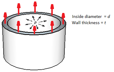
Following are the equations used to calculate the for the stress of a thin wall vessel with an internal pressure. The forces related are a consequence of pressure inside the cylindrical vessel.
HORIZONTAL WELD STRESS.
Considering pressure stresses only, the longitudinal weld force P, resulting from internal pressure p, acting on a thin wall tank of thickness t , length l , and diameter d is:
Where P= force tending to rupture the tank horizontally.
If a = area of metal resisting longitudinal force, then
Then
Where S = stress on the wall of the tank
Solving for t
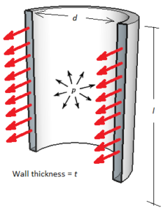
VERTICAL WELD STRESS.
Considering pressure stress only, the following analysis can be made.
Where P= force tending to rupture the tank vertically.
If a = area of metal resisting vertical force, then
Then
Where S = stress on the wall of the tank
Solving for t
![]() From this equations you can see that vertical stress is twice as high as horizontal stress. It is more likely that, in normal conditions, a tank shell will be teared apart first in the vertical than in the horizontal welds.
From this equations you can see that vertical stress is twice as high as horizontal stress. It is more likely that, in normal conditions, a tank shell will be teared apart first in the vertical than in the horizontal welds.
WELD SPACING SHOULD BE HIGHER RELATED TO VERTICAL WELDS THAN HORIZONTAL WELDS
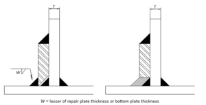
Figure 9-2. Shows how to weld Lapped Patch Repair Plates at the External Shell-to-bottom Joint.
When welding a low-type reinforcement to the shell, the size of the weld should be the lesser of repair plate thickness or bottom plate thickness
[adToAppearHere]
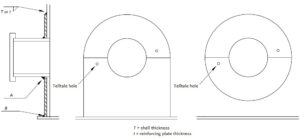
Figures 9-3A and 9-3B. Showing Typical Details for Addition of Reinforcing Plate to Existing Shell Penetration
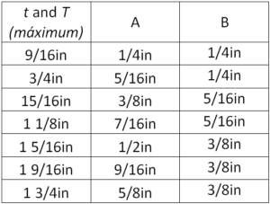 When welding reinforcements to existing unreinforced nozzles, you can do it low-type or circular type. In general, weld size is higher in the nozzle-reinforcement weld than in the reinforcemement-bottom weld, as you can see in the figure above.
Thanks a lot for reading and see you next week with another great article on tank inspection. If you want to receive this articles as they are posted, please write your email in the form below.

Latest comments
Hi Carlos, excellent effort and well done on producing this site. I am finding heps of useful info and tips. I only just found this today and have my exam in 3 weeks, but never too late! Thanks for taking the time and putting in all the hard work! Quick point I just notice on this page, minimum radious on shell insiert plates is actully 6". You may be mixed slightly with floor plates which is min 2". Keep up the great work! Cheers Dave
- Dave Laverick